
Structural Measurements on Outcrops (Right Hand Rule)
Geologists of the Ministère de l’Énergie et des Ressources naturelles (MERN), like many professionals in North America, use the right hand rule or right dip rule as a convention for taking structural measurements on outcrops. This convention is also used in databases of the Québec Geomining Information System (SIGÉOM) to store planar data (orientation and dip). The unit of measurement used is the degree.
Definition and Writing Rule
Definition
The right hand rule for the orientation of a planar structure can be represented as follows:
- The palm of the right hand is placed on the plane to be measured;
- All four fingers point down the slope;
- The open thumb indicates the orientation of the plane.
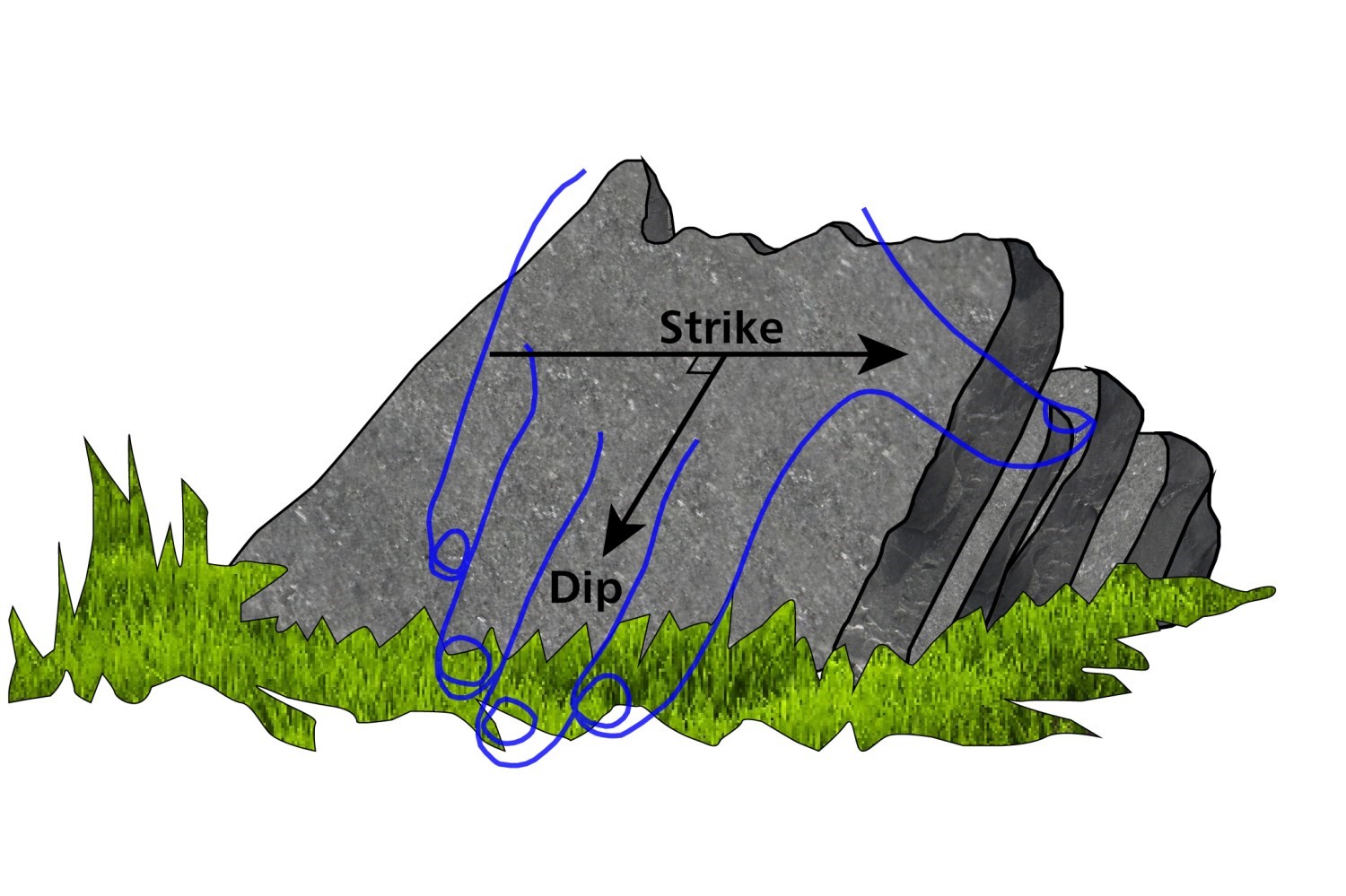
The right hand rule can also be visualized as follows: the orientation of a plane is the orientation towards which the observer looks when the dip is to the right.
Planar Structures
Orientation (strike): corresponds to the azimuth of the horizontal line perpendicular to the line of greatest slope of the plane. The orientation is measured in relation to geographic north in a clockwise direction on the horizontal plane. The values are between 0° and 360° where 360° indicates North.
Dip (dip): corresponds to the angle between the line of greatest slope of the plane and the horizontal. The value of the dip is between 0° (horizontal plane) and 90° (vertical plane).
Linear Structures
Orientation (trend): corresponds to the azimuth of the vertical plane that contains the line in the direction of its plunge. The orientation is measured in relation to geographic north in a clockwise direction on a horizontal plane. The values are between 0° and 360° where 360° indicates North.
Dip (plunge): corresponds to the angle of the lineation with respect to the horizontal. The value of the plunge is between 0° and 90° and may not exceed the value of the dip of the plane on which it is measured.
Glacial erosion marks (e.g. glacial striations) are a special case of linear measurement. The marks left by glacial erosion are considered as a line and their measurement consists of determining the azimuth of their orientation in the direction of movement (if known). The orientation is measured in relation to geographic north in a clockwise direction on a horizontal plane. The values are between 0° and 360° where 360° indicates North. The plunge is not measured.
Writing Rule
The measurements of planes and lines are noted as follows:
- Plane: strike/dip (0°-360°/0°-90°)
- Line: trend/plunge (0°-360°/0°-90°)
- Glacial erosion marks: orientation (1°-360°)
Methods of Measuring Structural Components on Outcrops
Orientation, dip and plunge are measured on outcrops with a compass. Brunton Transit compasses are the most commonly used at the MERN. They are set to compensate for magnetic declination in the area being mapped. The use of an aluminium plate or another rigid, non-magnetic planar object (e.g. a notebook) is often necessary to properly measure structures. The aluminium plate is however recommended and is generally used at the MERN. The plate allows for more accurate and repeatable measurements.
Measurement of a Planar Structure
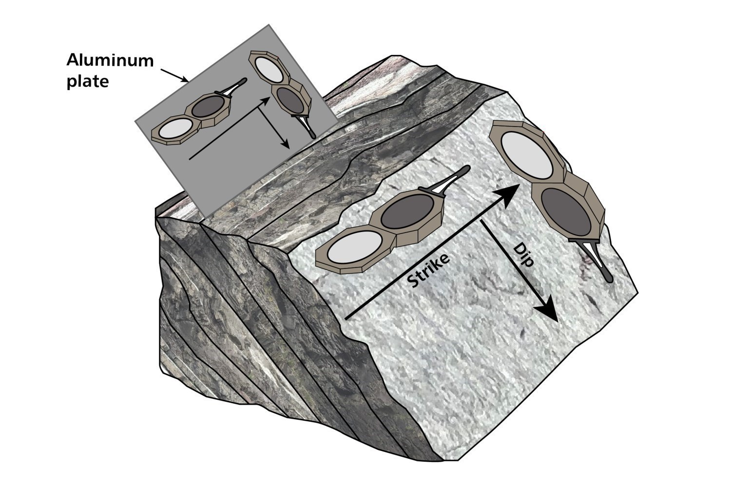
The measurement of a plane is done in two steps. If necessary, the aluminium plate is used to mark the surface to be measured. In the first step, the compass is placed against the aluminium plate and brought into a horizontal position using the built-in spirit level. The compass sight must indicate the direction of the azimuth to be measured. In other words, the compass sight replaces the thumb of the right hand. Once the compass needle has stabilized, the value of the azimuth of the plane (orientation) can be read by observing the north end of the needle. In a second step, the long side of the compass is placed against the plate with the sight in the direction of the line of greatest slope of the plane (i.e. perpendicular to the previously measured orientation). Using the clinometer, the inclination of the plane (dip) is measured. The level of the clinometer must be horizontal.
Measurement of a Linear Structure
There are two main methods of measuring a linear structure.
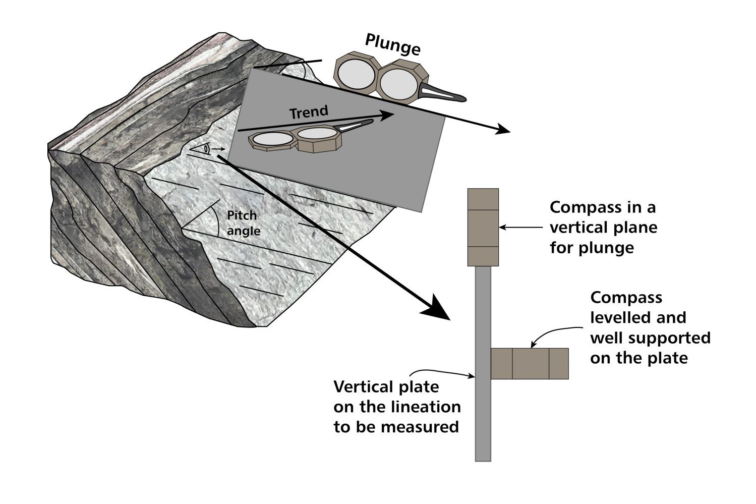
The first and most common method is the direct measurement of the line. This is done in two steps. First, one edge of the aluminium plate is placed against the line to be measured, parallel to it. At this stage, it may be useful to first draw the line with chalk. This line then forms an axis or hinge around which the plate can be rotated. The compass is placed against the aluminium plate with the sight pointing in the plunge direction of the line. Making sure that the edge of the plate always remains against the line to be measured, the plate is rotated until it is in a vertical position using the spirit level. The orientation of the line can then be measured, which is indicated by the north of the compass needle once it has stabilized. In a second step, while keeping the plate in the same position, the compass is placed against the edge of the plate parallel to the lineation. With the help of the clinometer, the plunge of the line can be read.
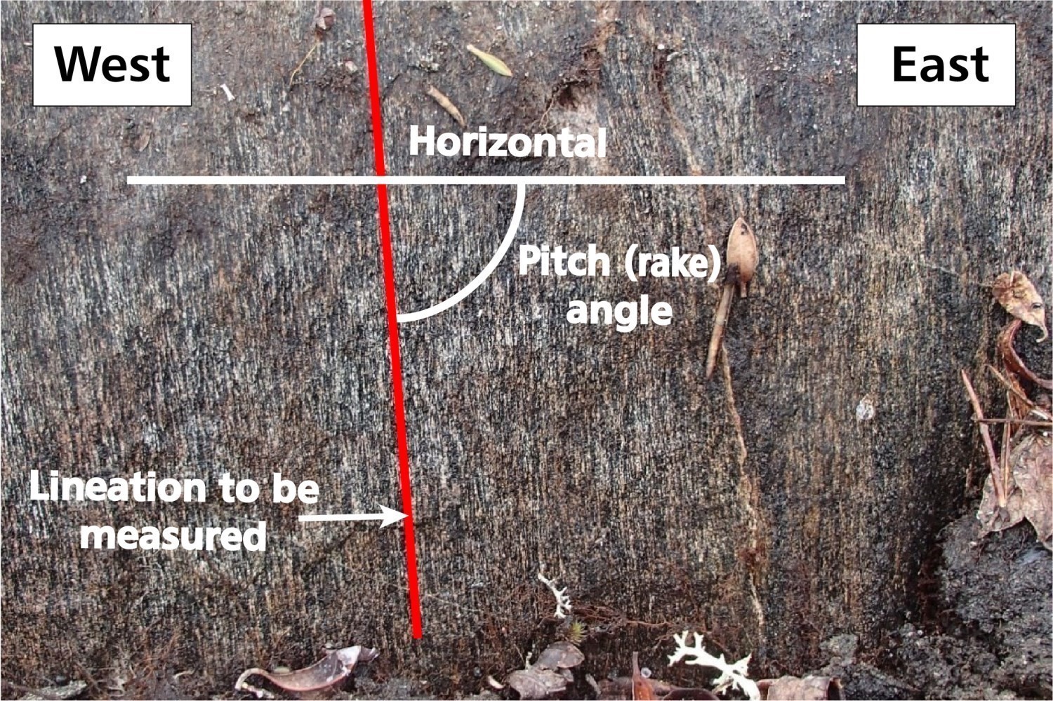
The second method is indirect and involves measuring the angle between the line to be measured and a horizontal line (i.e. the orientation) on the plane that bears it. This angle is called the pitch angle (or rake in the United States) and must be between 0° and 90°. The measurement is made with a protractor or a Douglas after having drawn the lineation and the orientation of the plane with chalk. It corresponds to the acute angle between the measured lineation and the horizontal. The plunge direction of the lineation is also recorded, as it can have two orientations. For example, a line carried by a plane oriented at 300/45 may have a pitch angle towards the NW if the angle was measured from the direction 300°, or an angle towards the SE if the angle was measured from the direction 120°. The complete measurement of a pitch angle is thus 30°SW, 62°NW, etc. To use this method, it is essential to know the orientation (direction and dip) of the plane carrying the line. The conversion of a pitch angle into the orientation and plunge of a lineation is done by means of a stereographic grid or software and requires that the measurement of the bearing plane is known.
Glacial Erosion Marks
Glacial erosion marks are observed and measured on outcrops during fieldwork. Systematic surveys of this type are even carried out during Quaternary surveys. The orientation of the different types of erosion marks can also be used to determine the direction and sense of ice flow.
To measure a glacial erosion mark, a rigid, elongated object (e.g. a pencil) can be used to mark the line to be measured on the outcrop surface. In cases where more than one generation of erosion marks is observed, a pencil is placed over each generation of marks to differentiate them and to facilitate subsequent measurements. The compass is placed over the line to be measured and levelled with the built-in spirit level. The compass sight is aligned with the line to be measured. In cases where the polarity (direction of movement) is known, the compass sight should point downstream of the ice flow. After the compass needle has stabilized, the north end of the needle indicates the azimuth value of the line.
Finally, it is recommended that directional measurements (planar and linear) be corrected to counteract the effects of magnetism induced by the presence of magnetite in the rocks. On sunny days, it is possible to measure the orientation of the sun at the site of the structural measurement, taking care to note the time and date of the measurement. This is done by placing an object (e.g. a pencil) vertically on the outcrop and tracing the shadow cast by the object with chalk. The angle between the direction of the plane and that of the shadow is then measured. The measurement can then be corrected by consulting solar ephemeris on specialized websites (e.g. https://gml.noaa.gov/grad/solcalc/) where the position of the sun in the sky is determined anywhere on earth at any time of day. Specialized applications also exist for tablets and smart phones.
SIGÉOM Databases
In SIGÉOM databases, orientation, dip and plunge values are available for the following geoscientific features:
| Theme | Geoscientific Entity | Entity Class (GDB) | Shape file |
|---|---|---|---|
| Bedrock | Planar structure | F3E02_STRUCTURE_PLANAIRE | Planar structure |
| Linear structure | F3E03_STRUCTURE_LINEAIRE_PLIS | Linear structure folds | |
| Drilling | Diamond drilling | F5E02_FORAGE_DIAMANT | Diamond drilling |
| Quaternary Geology | Glacial erosion forms | F10E22_MARQU_EROSI_GLACI | Glacial erosion forms |
The following table shows the names of the fields in which structural measurements are stored for each of the entities, as well as the allowed values:
| Geoscientific Entity | Field Name | Description | Allowed Values |
|---|---|---|---|
| Planar structure | AZMT | Azimuth of the plane's orientation |
0 - 360 The 360 value indicates North. The 0 value indicates an horizontal plane. |
| PEND | Plane's dip |
0 - 90 and 99 A value of 99 indicates that the dip is indeterminate. In this case, the azimuth value is approximate. It may represent, for example, the trace of foliation on the surface of a flat outcrop. |
|
| Linear structure | AZMT | Azimuth of the lineation's orientation |
1 - 360 The 360 value indicates North. |
| PLON | Lineation's plunge |
0 - 90 and 99 The value 0 indicates a horizontal lineation. In this case, there are two possible values for the azimuth, both 180° opposite each other. A value of 99 indicates that the dip is indeterminate. |
|
| DIamond drilling | AZMT_DEPR | Starting azimuth of the drilling at the collar |
0 - 360 The 360 value indicates North. The 0 value indicates an horizontal plane. |
| AZMT_FIN | Azimuth at the end of the drilling | ||
| PLON_DEPR | Plunge at the start of the drilling |
0 - 90 and 99 A value of 99 indicates that the dip is indeterminate. |
|
| PLON_FIN | Plunge at the end of the drilling | ||
| Glacial erosion mark | AZMT | Azimuth of the erosion mark's orientation |
1 - 360 The 360 value indicates North. When the polarity is known, the azimuth indicates the direction of the ice flow. Otherwise, there are two possible values for the azimuth, both 180° opposite each other. |
Map Symbols
Planar, linear and drilling structures are represented on geological maps and the interactive map by specific symbols (see DV 2014-06 for details). In general, the dip of planar structures is indicated by a short line perpendicular to a longer line representing the strike. Only the dip or plunge of linear structures is shown on maps. Using the right hand rule for planar structures, the azimuth of the orientation is deduced. On the SIGÉOM interactive map, the symbols of structural measurements are searchable and the azimuth, dip and plunge values are shown.
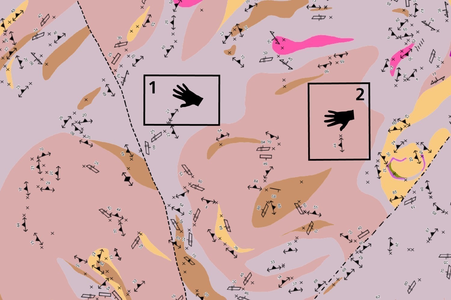
Example of using the right hand rule to determine the direction the orientation of planar structures on SIGÉOM geological maps. In Box 1, the orientation of the planar structure is towards the southwest (SW); in Box 2, the orientation of the planar structure is towards the south.
Credits
|
Ghyslain Roy, P. Geo. (redaction) Yannick Daoudene, P. Geo., Ph.D.; James Moorhead, P. Geo., M.Sc. (critical review); Claude Dion, Eng., M.Sc. (editing); Céline Dupuis, P. Geo., Ph.D. (English version) |
References
Daigneault, R., 1991. Déformation et cisaillement, concepts et applications. UQAC, MRN; DV 89-16, 57 pages.
Holcombe, R.J., 2016. Mapping and structural geology in mineral exploration: where theory hits the fan. HCOV Global; 233 pages. (source)